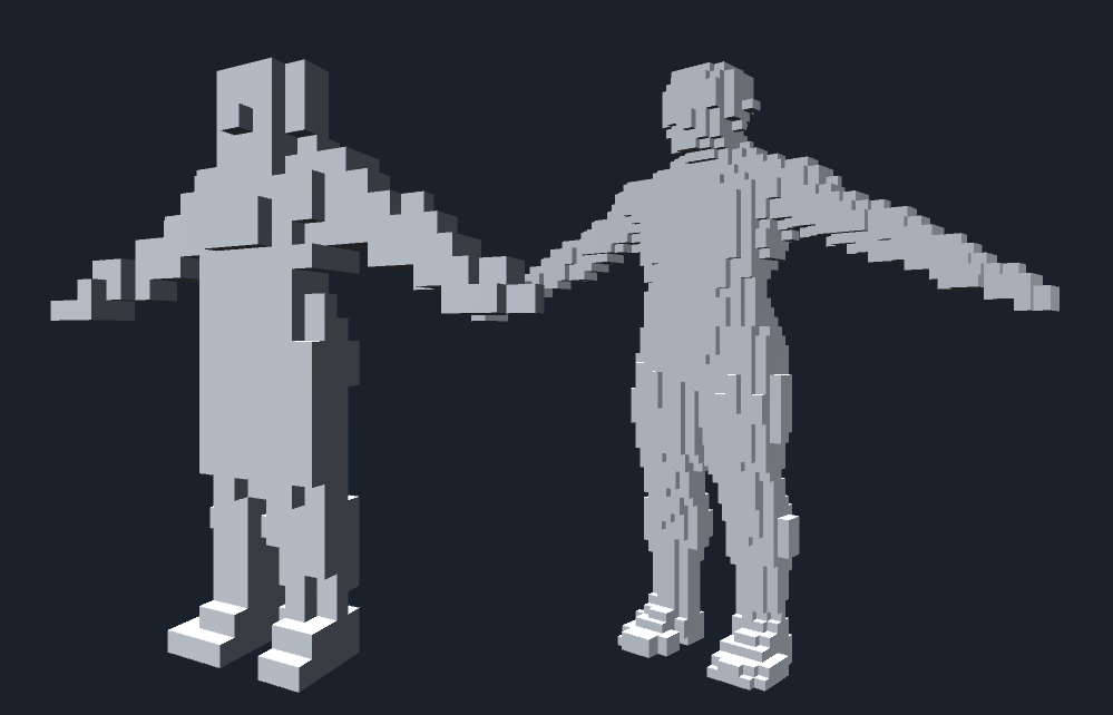
Figure 1.1: Differences in voxel resolution
In this chapter, we will develop GPU Voxelizer, a program that uses GPU to make voxels of meshes in real time.
The sample in this chapter is "RealTime GPUBasedVoxelizer" from
https://github.com/IndieVisualLab/UnityGraphicsProgramming2
.
First, after confirming the voxelization procedure and the obtained results based on the implementation on the CPU, we will explain the implementation method on the GPU and introduce an example of effects that apply high-speed voxelization.
A voxel represents a basic unit in a three-dimensional reciprocal lattice space. It can be imagined as an increase in the dimension of the pixel (Pixel) used as the basic unit of the two-dimensional normal lattice space, and it is named Voxel in the sense of Pixel with Volume. Voxels can express volume, and each voxel may have a data format that stores values such as concentration, which may be used for visualization and analysis of medical and scientific data.
Also, in the game, Minecraft * 1 is listed as using voxels.
It takes time to create a detailed model and stage, but if it is a voxel model, it can be created with relatively little effort, and even if it is free, there are excellent editors such as MagicaVoxel * 2, and the model looks like a 3D pixel art. Can be created.
[*1] https://minecraft.net
[*2] http://ephtracy.github.io/
I will explain the voxelization algorithm based on the implementation on the CPU. The CPU implementation is described in CPUVoxelizer.cs.
The general flow of voxelization is as follows.
Voxelization in CPU is a static function of CPUVoxelizer class
CPUVoxelizer.cs
public class CPUVoxelizer
{
    public static void Voxelize (
        Mesh mesh,
        int resolution,
        out List<Vector3> voxels,
        out float unit,
        bool surfaceOnly = false
    ) {
    ...
    }
    ...
}
Execute by calling. If you specify the mesh and resolution you want to voxel in the argument and execute it, the voxel array voxels and the unit representing the size of one voxel are returned via the reference argument.
In the following, I will explain what is done inside the Voxelize function along the general flow.
To make voxels, first set the voxel resolution. The finer the resolution, the smaller the cube will be built, so a detailed voxel model can be generated, but it requires more calculation time.
Figure 1.1: Differences in voxel resolution
Specifies the range to voxelize the target mesh model. If you specify the BoundingBox (the smallest rectangular parallelepiped that fits all the vertices of the model) of the mesh model as the voxelization range, you can voxelize the entire mesh model.
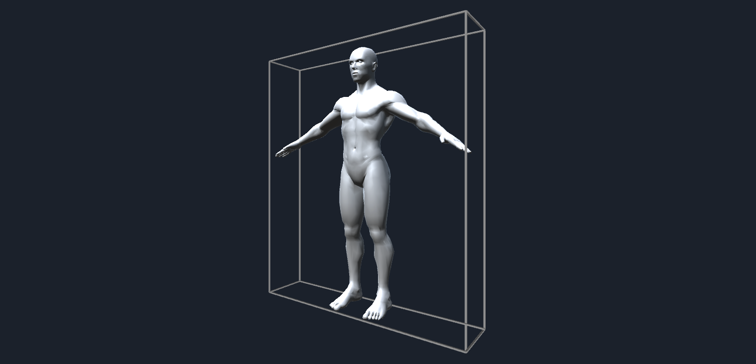
Figure 1.2: Mesh BoundingBox
It should be noted here that if the BoundingBox of the mesh model is used as it is as the voxelization range, problems will occur when voxelizing a mesh that has a surface that exactly overlaps the BoundingBox, such as a Cube mesh. ..
As will be described in detail later, when voxels are created, the intersection of the triangles and voxels that make up the mesh is determined. However, if the triangles and voxel surfaces overlap exactly, the intersection may not be determined correctly.
Therefore, the range in which the BoundingBox of the mesh model is expanded by "half the length of the unit length that constitutes one voxel" is specified as the voxelization range.
CPUVoxelizer.cs
mesh.RecalculateBounds();
var bounds = mesh.bounds;

// Calculate the unit lengths that make up one voxel from the specified resolution
float maxLength = Mathf.Max(
    bounds.size.x,
    Mathf.Max(bounds.size.y, bounds.size.z)
);
unit = maxLength / resolution;

// Half the unit length
var hunit = unit * 0.5f;

// "Half the length of the unit length that makes up one voxel" Expanded range
// Scope of voxels

// Minimum value of bounds to voxelize
var start = bounds.min - new Vector3 (unit, unit, unit);

// Maximum value of bounds to voxelize
var end = bounds.max + new Vector3 (unit, unit, unit);

// Size of bounds to voxelize
var size = end - start;
The sample code provides a Voxel_t structure as a structure that represents voxels.
Voxel.cs
[StructLayout(LayoutKind.Sequential)]
public struct Voxel_t {
    public Vector3 position; // Voxel position
    public uint fill; // Flag whether voxels should be filled
    public uint front; // Flag whether the triangle that intersects the voxel is the front when viewed from the determined direction
    ...
}
A three-dimensional array of this Voxel_t is generated, and voxel data is stored in it.
CPUVoxelizer.cs
// Determine the size of 3D voxel data based on the unit length of voxels and the range of voxelization
var width = Mathf.CeilToInt(size.x / unit);
var height = Mathf.CeilToInt(size.y / unit);
var depth = Mathf.CeilToInt(size.z / unit);
var volume = new Voxel_t[width, height, depth];
Also, in order to refer to the position and size of each voxel in the subsequent processing, generate an AABB array that matches the 3D voxel data in advance.
CPUVoxelizer.cs
var boxes = new Bounds[width, height, depth];
var voxelUnitSize = Vector3.one * unit;
for(int x = 0; x < width; x++)
{
    for(int y = 0; y < height; y++)
    {
        for(int z = 0; z < depth; z++)
        {
            var p = new Vector3(x, y, z) * unit + start;
            var aabb = new Bounds(p, voxelUnitSize);
            boxes[x, y, z] = aabb;
        }
    }
}
AABB (Axis-Aligned Bounding Box) is a rectangular parallelepiped boundary figure whose sides are parallel to the XYZ axes in 3D space.
AABB is often used for collision detection, and in some cases it is used for collision detection between two meshes or for simple collision detection between a certain mesh and a light beam.
If you want to make a strict collision detection for a mesh, you have to make a judgment for all the triangles that make up the mesh, but if you only use AABB including the mesh, you can calculate at high speed, which is convenient.
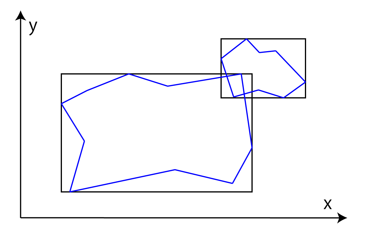
Figure 1.3: Collision detection between AABBs of two polygonal objects
Generate voxels located on the surface of the mesh as shown in the figure below.
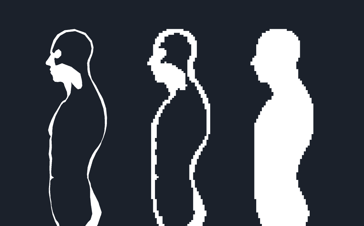
Figure 1.4: First, generate voxels located on the surface of the mesh, and then generate voxels based on it so as to fill the contents of the mesh.
To find the voxels located on the surface of the mesh, it is necessary to determine the intersection of each of the triangles that make up the mesh and the voxels.
SAT (Separating Axis Theorem) is used to determine the intersection of a triangle and a voxel. The intersection determination algorithm using SAT is not limited to triangles and voxels, but can be used for general purposes as intersection determination between convex surfaces.
The SAT has proved that:
If you want a straight line with the entire object A on one side and the entire object B on the other, object A and object B will not intersect. Such a straight line that separates two objects is called a separation straight line, and the separation line is always orthogonal to the separation axis.
If the SAT finds an axis (separation axis) where the projections of two convex surfaces do not overlap, it can be derived that the two convex surfaces do not intersect because there is a straight line that separates the two convex surfaces. Conversely, if no separation axis is found, it can be determined that the two convex surfaces intersect. (If the shape is concave, it may not intersect even if the separation axis is not found.)
When a convex shape is projected onto an axis, the shadow of that shape appears as if it were projected onto a line that represents that axis. This can be represented as a line segment on the axis and can be represented by the range interval [min, max].
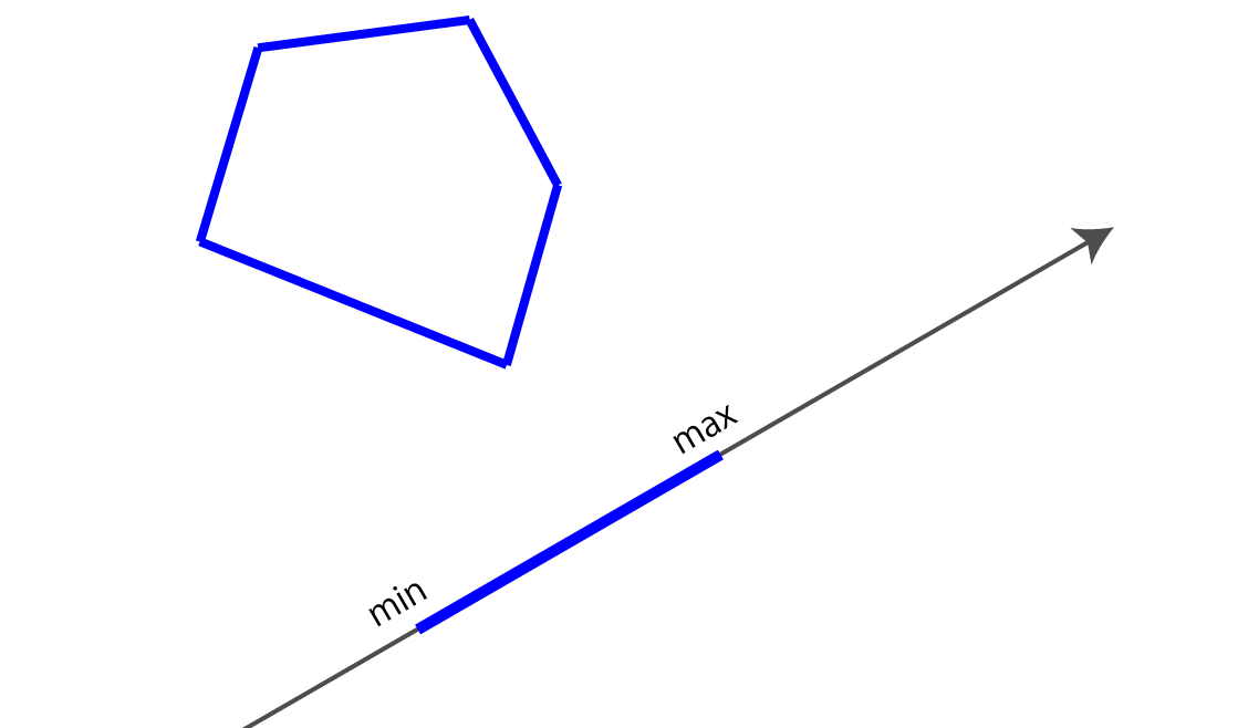
Figure 1.5: Convex shape projected onto a certain axis and the range of the convex shape projected on the axis (min, max)
As shown in the figure below, when there are two convex separation straight lines, the projection sections of the convex shape with respect to the separation axis orthogonal to the straight lines do not overlap.
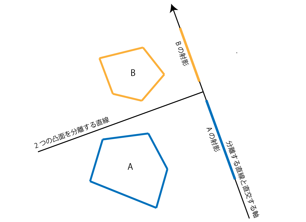
Figure 1.6: If there is a straight line that separates the two convex shapes, the projection sections on the axes orthogonal to the straight line do not overlap.
However, even with the same two convex surfaces, projections on other non-separable axes may overlap, as shown in the figure below.
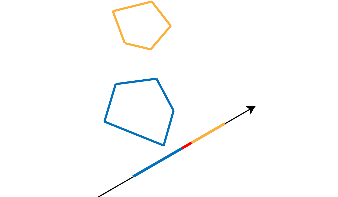
Figure 1.7: When projecting on an axis orthogonal to a straight line that does not separate the two convex shapes, the projections may overlap.
For some shapes, the possible axes of separation are obvious, and to determine the intersection of two such shapes A and B, two for each of the possible axes of separation. Crossing can be determined by projecting the shape and checking whether the two projection sections [Amin, Amax] and [Bmin, Bmax] overlap each other. Expressed in the formula, if Amax <Bmin or Bmax <Amin, the two intervals do not overlap.
The axis that can be the separation axis between the convex surfaces is
From this, the axis that can be the separation axis between the triangle and the voxel (AABB) is
Therefore, for each of these 13 axes, the intersection of the triangle and the voxel is determined by determining whether or not the projections overlap.
Since it may be useless to judge the intersection of one triangle and all voxel data, calculate the AABB including the triangle and judge the intersection with the voxels contained in it. ..
CPUVoxelizer.cs
// Calculate the triangle AABB
var min = tri.bounds.min - start;
var max = tri.bounds.max - start;
int iminX = Mathf.RoundToInt(min.x / unit);
int iminY = Mathf.RoundToInt(min.y / unit);
int iminZ = Mathf.RoundToInt(min.z / unit);
int imaxX = Mathf.RoundToInt(max.x / unit);
int imaxY = Mathf.RoundToInt(max.y / unit);
int imaxZ = Mathf.RoundToInt(max.z / unit);
iminX = Mathf.Clamp(iminX, 0, width - 1);
iminY = Mathf.Clamp(iminY, 0, height - 1);
iminZ = Mathf.Clamp(iminZ, 0, depth - 1);
imaxX = Mathf.Clamp(imaxX, 0, width - 1);
imaxY = Mathf.Clamp(imaxY, 0, height - 1);
imaxZ = Mathf.Clamp(imaxZ, 0, depth - 1);

// Judge the intersection with voxels in the triangular AABB
for(int x = iminX; x <= imaxX; x++) {
    for(int y = iminY; y <= imaxY; y++) {
        for(int z = iminZ; z <= imaxZ; z++) {
            if(Intersects(tri, boxes[x, y, z])) {
                ...
            }
        }
    }
}
The Intersects (Triangle, Bounds) function is used to determine the intersection of a triangle and a voxel.
CPUVoxelizer.cs
public static bool Intersects(Triangle tri, Bounds aabb)
{
    ...
}
In this function, the intersection judgment is performed for the above 13 axes, but the three normals of AABB are known (since they have sides along the XYZ axes, they are simply the X axis (1, 0, 0), Y-axis (0, 1, 0), Z-axis (0, 0, 1) normals), or so that the center of AABB is at the origin (0, 0, 0) The intersection judgment is optimized by translating the coordinates of the triangle and AABB.
CPUVoxelizer.cs
// Get the center coordinates of AABB and the extents of each side
Vector3 center = aabb.center, extents = aabb.max - center;

// Translate the coordinates of the triangle so that the center of AABB is at the origin (0, 0, 0)
Vector3 v0 = tri.a - center,
        v1 = tri.b - center,
        v2 = tri.c - center;

// Get the vector representing the three sides of the triangle
Vector3 f0 = v1 - v0,
        f1 = v2 - v1,
        f2 = v0 - v2;
First, we will make an intersection judgment based on the nine cross products obtained from the combination of the three sides of the triangle and the three orthogonal sides of AABB, but the direction of the three sides of AABB will be the XYZ axes. You can take advantage of the parallelism and omit the calculation to get the cross product.
CPUVoxelizer.cs
// Since the sides of AABB are the direction vectors x (1, 0, 0), y (0, 1, 0), z (0, 0, 1), respectively,
// You can get 9 different cross products without doing any calculations
Vector3
    a00 = new Vector3 (0, -f0.z, f0.y), // Cross product of X axis and f0
    a01 = new Vector3 (0, -f1.z, f1.y), // X and f1
    a02 = new Vector3(0, -f2.z, f2.y), // Xとf2
    a10 = new Vector3(f0.z, 0, -f0.x), // Yとf0
    a11 = new Vector3(f1.z, 0, -f1.x), // Yとf1
    a12 = new Vector3(f2.z, 0, -f2.x), // Yとf2
    a20 = new Vector3(-f0.y, f0.x, 0), // Zとf0
    a21 = new Vector3(-f1.y, f1.x, 0), // Zとf1
    a22 = new Vector3(-f2.y, f2.x, 0); // Zとf2

// Perform intersection judgment for 9 axes (described later)
// (If any one of the axes does not intersect, the triangle and AABB do not intersect, so false is returned)
if (
    !Intersects(v0, v1, v2, extents, a00) ||
    !Intersects(v0, v1, v2, extents, a01) ||
    !Intersects(v0, v1, v2, extents, a02) ||
    !Intersects(v0, v1, v2, extents, a10) ||
    !Intersects(v0, v1, v2, extents, a11) ||
    !Intersects(v0, v1, v2, extents, a12) ||
    !Intersects(v0, v1, v2, extents, a20) ||
    !Intersects(v0, v1, v2, extents, a21) ||
    !Intersects(v0, v1, v2, extents, a22)
)
{
    return false;
}
The following function projects the triangle and AABB on these axes to determine the intersection.
CPUVoxelizer.cs
protected static bool Intersects(
    Vector3 v0,
    Vector3 v1,
    Vector3 v2,
    Vector3 extents,
    Vector3 axis
)
{
    ...
}
The point to note here is that the optimization is performed by bringing the center of AABB to the origin. It is not necessary to project all the vertices of AABB on the axis, and the interval on the axis can be obtained simply by projecting the vertex with the maximum value for the XYZ axes of AABB, that is, the extents of half the length of each side. I will.
The value r obtained by projecting extents represents the interval [-r, r] on the projection axis of AABB, which means that the projection can be calculated only once for AABB.
CPUVoxelizer.cs
// Project the vertices of the triangle on the axis
float p0 = Vector3.Dot(v0, axis);
float p1 = Vector3.Dot(v1, axis);
float p2 = Vector3.Dot(v2, axis);

// Project the extents with the maximum value for the XYZ axes of AABB on the axis to get the value r
// Since the section of AABB is [-r, r], it is not necessary to project all vertices for AABB.
float r =
    extents.x * Mathf.Abs(axis.x) +
    extents.y * Mathf.Abs(axis.y) +
    extents.z * Mathf.Abs(axis.z);

// Triangular projection section
float minP = Mathf.Min(p0, p1, p2);
float maxP = Mathf.Max(p0, p1, p2);

// Determine if the triangular section and the AABB section overlap
return !((maxP < -r) || (r < minP));
Next to the discrimination based on the nine cross products, the discrimination is performed based on the three normals of AABB.
Using the characteristic that the normal of AABB is parallel to the XYZ axes, the coordinate values are translated so as to bring the center of AABB to the origin, so the minimum value for the XYZ component of each vertex of the triangle is simply. Crossing judgment can be performed simply by comparing the maximum value and extends.
CPUVoxelizer.cs
// X axis
if (
    Mathf.Max(v0.x, v1.x, v2.x) < -extents.x ||
    Mathf.Min(v0.x, v1.x, v2.x) > extents.x
)
{
    return false;
}

// Y axis
if (
    Mathf.Max (v0.y, v1.y, v2.y) <-extents.y ||
    Mathf.Min (v0.y, v1.y, v2.y)> extents.y
)
{
    return false;
}

// Z axis
if (
    Mathf.Max(v0.z, v1.z, v2.z) < -extents.z ||
    Mathf.Min(v0.z, v1.z, v2.z) > extents.z
)
{
    return false;
}
Lastly, regarding the triangular normal, we are making a judgment about the intersection of the Plane with the triangular normal and AABB.
CPUVoxelizer.cs
var normal = Vector3.Cross(f1, f0).normalized;
var pl = new Plane(normal, Vector3.Dot(normal, tri.a));
return Intersects(pl, aabb);
The Intersects (Plane, Bounds) function determines the intersection of Plane and AABB.
CPUVoxelizer.cs
public static bool Intersects(Plane pl, Bounds aabb)
{
    Vector3 center = aabb.center;
    var extents = aabb.max - center;

    // Project the extents on the normal of Plane
    var r =
        extents.x * Mathf.Abs(pl.normal.x) +
        extents.y * Mathf.Abs (pl.normal.y) +
        extents.z * Mathf.Abs(pl.normal.z);

    // Calculate the distance between Plane and the center of AABB
    var s = Vector3.Dot(pl.normal, center) - pl.distance;

    // Determine if s is in the range [-r, r]
    return Mathf.Abs(s) <= r;
}
If the intersecting voxels can be determined for one triangle, the fill flag of the voxel data is set, and the front flag is set to indicate whether the triangle is front or back when viewed from the determined direction. (The front flag will be described later)
Some voxels may intersect both front-facing and back-facing triangles, in which case the front flag should prioritize the back.
CPUVoxelizer.cs
if(Intersects(tri, boxes[x, y, z])) {
    // Get voxels at intersecting (x, y, z)
    var voxel = volume[x, y, z];

    // Set the voxel position
    voxel.position = boxes[x, y, z].center;

    if(voxel.fill & 1 == 0) {
        // If the voxels are not yet filled
        // Flag the triangle that intersects the voxel for the front
        voxel.front = front;
    } else {
        // If the voxel is already filled with other triangles
        // Give priority to the flag on the back
        voxel.front = voxel.front & front;
    }

    // Flag to fill voxels
    voxel.fill = 1;
    volume[x, y, z] = voxel;
}
The front flag is required for the "process to fill the contents of the mesh" described later, and sets whether it is the front or the back when viewed from the "direction to fill the contents".
In the sample code, the contents of the mesh are filled in the forward (0, 0, 1) direction, so it is determined whether the triangle is in front when viewed from forward (0, 0, 1).
If the inner product of the normal of the triangle and the direction to fill the voxels is 0 or less, it means that the triangle is the front when viewed from that direction.
CPUVoxelizer.cs
public class Triangle {
    public Vector3 a, b, c; // 3 points that make up a triangle
    public bool frontFacing; // Flag whether the triangle is a surface when viewed from the direction of filling the voxels
    public Bounds bounds; // Triangular AABB

    public Triangle (Vector3 a, Vector3 b, Vector3 c, Vector3 dir) {
        this.a = a;
        this.b = b;
        this.c = c;

        // Determine if the triangle is front when viewed from the direction of filling the voxels
        var normal = Vector3.Cross(b - a, c - a);
        this.frontFacing = (Vector3.Dot(normal, dir) <= 0f);

        ...
    }
}
Now that we have calculated the voxel data located on the mesh surface, we will fill in the inside.
Figure 1.8: State after generating voxel data located on the mesh surface
Search for voxels that are facing forward when viewed from the direction of filling the voxels.
Empty voxels will pass through as shown in the figure below.
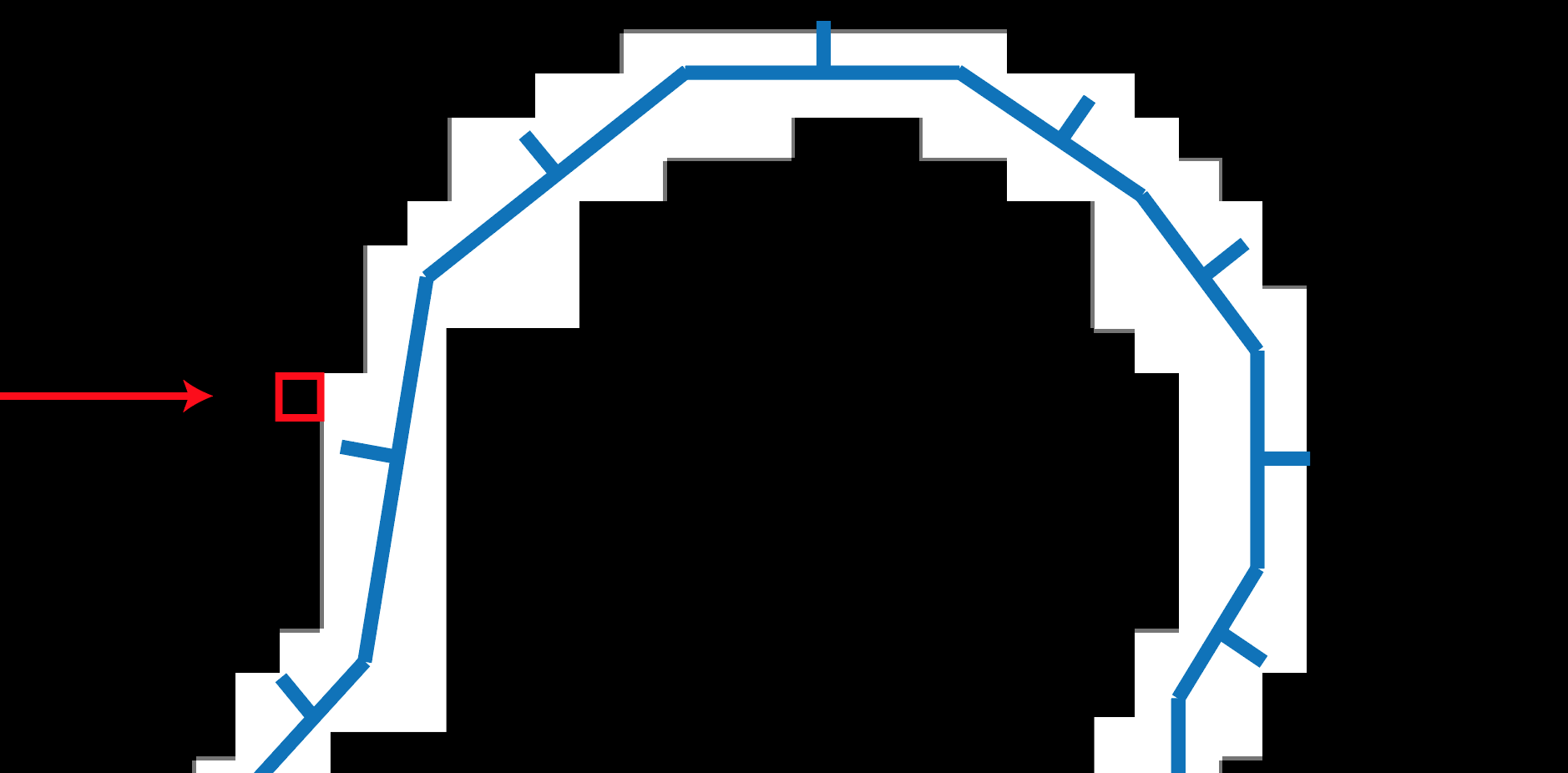
Figure 1.9: Search for voxels facing forward when viewed from the voxel-filling direction Empty voxels pass through (arrows fill voxels and frames represent voxel positions being searched)
Once you find a voxel that is facing the front, proceed through the voxel that is facing the front.
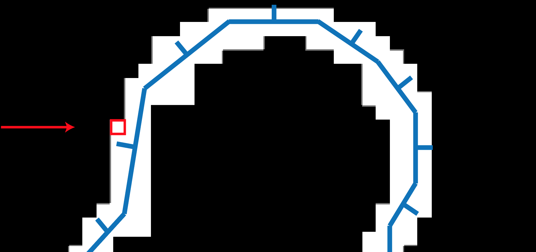
Figure 1.10: Finding a voxel facing the front (the line coming out of the mesh surface is the mesh normal, and in the figure the mesh normal and the voxel filling direction are opposite, so the position of the frame You can see that the voxel is located in the front)
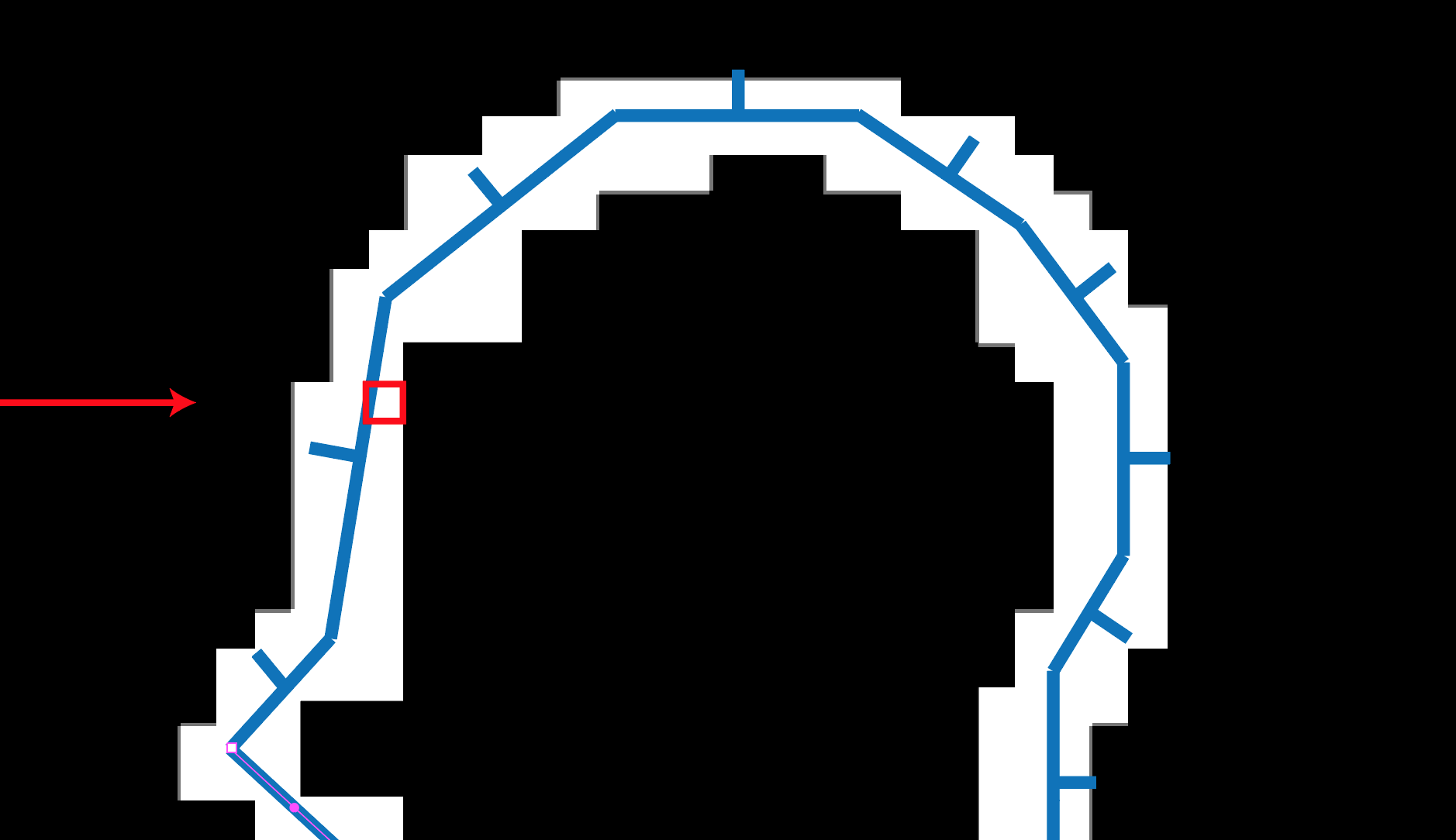
Figure 1.11: Go through a voxel facing the front
After passing through the voxels facing the front, you will reach the inside of the mesh.
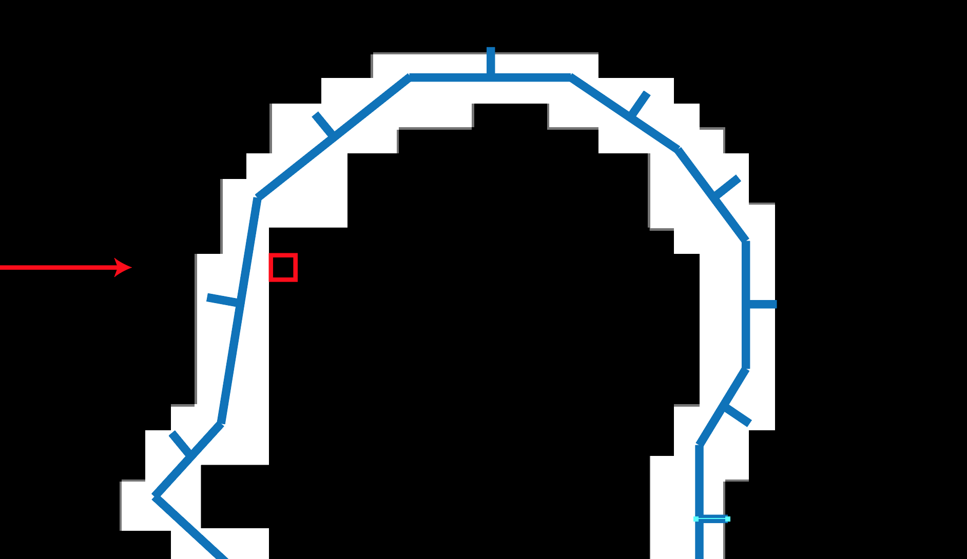
Figure 1.12: Passing through a voxel facing the front and reaching the inside of the mesh
Proceed through the inside of the mesh and fill the voxels that have arrived.
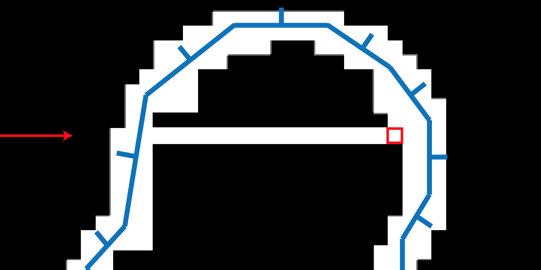
Figure 1.13: Fill the reached voxels as they fill the inside of the mesh
Then, when you reach the voxel facing the back when viewed from the direction of filling the voxel, you can see that the inside of the mesh has been filled. Go through the voxels facing the back, and when you reach the outside of the mesh, you will start searching for the voxels facing the front again.
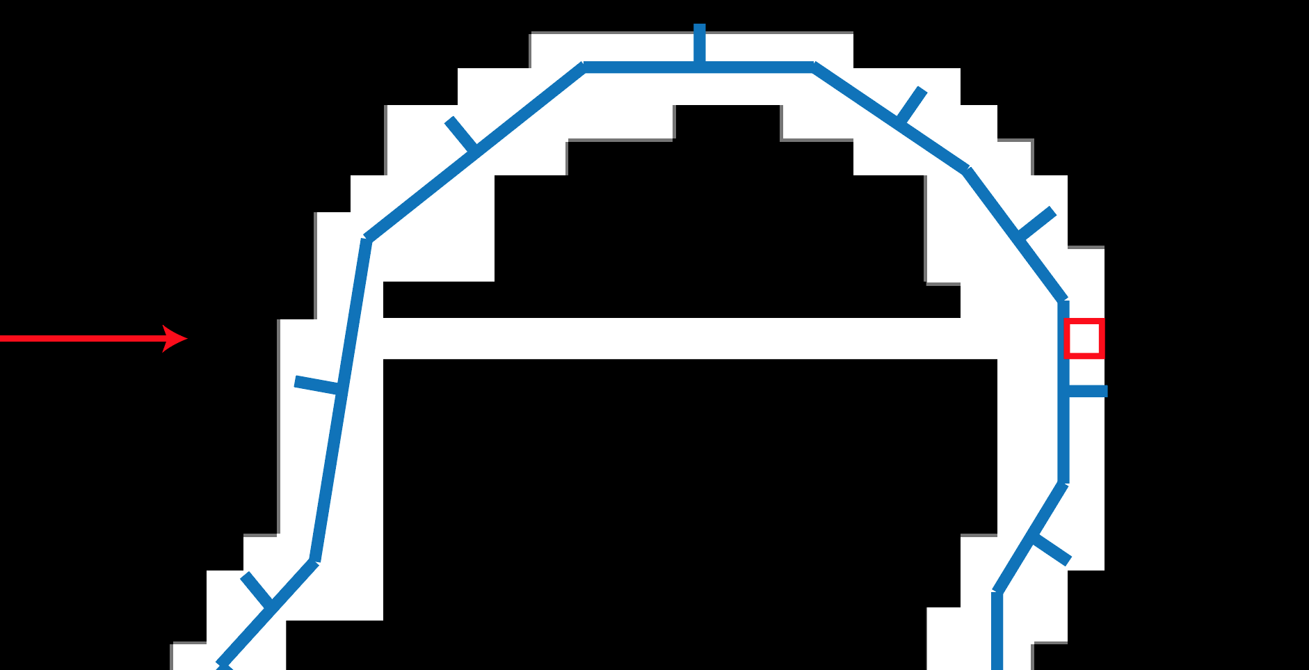
Figure 1.14: Proceed through the voxel facing backwards from the direction of filling the voxel and then out of the mesh
As determined in the previous section, the inside is filled in the forward (0, 0, 1) direction, so in a 3D voxel array, the inside is filled in the z direction.
The process of filling the contents starts from volume [x, y, 0] on the front side in the z direction and proceeds to volume [x, y, depth -1].
CPUVoxelizer.cs
// Fill the inside of the mesh
for(int x = 0; x < width; x++)
{
    for(int y = 0; y < height; y++)
    {
        // Fill the inside of the mesh from the front side in the z direction to the back side
        for(int z = 0; z < depth; z++)
        {
            ...
        }
    }
}
Based on the front flag (front or back in the z direction) already written in the voxel data, the process proceeds according to the above-mentioned flow of filling voxels.
CPUVoxelizer.cs
...
// Fill the inside of the mesh from the front side in the z direction to the back side
for(int z = 0; z < depth; z++)
{
    // Ignore if (x, y, z) is empty
    if (volume[x, y, z].IsEmpty()) continue;

    // Go through the voxels located in front
    int ifront = z;
    for(; ifront < depth && volume[x, y, ifront].IsFrontFace(); ifront++) {}

    // If you go to the end, it's over
    if(ifront >= depth) break;

    // Find the voxels located on the back
    int iback = ifront;

    // Go inside the mesh
    for (; iback < depth && volume[x, y, iback].IsEmpty(); iback++) {}

    // If you go to the end, it's over
    if (iback >= depth) break;

    // Determine if (x, y, iback) is on the back
    if(volume[x, y, iback].IsBackFace()) {
        // Follow the voxels located on the back
        for (; iback < depth && volume[x, y, iback].IsBackFace(); iback++) {}
    }

    // Fill voxels from (x, y, ifront) to (x, y, iback)
    for(int z2 = ifront; z2 < iback; z2++)
    {
        var p = boxes [x, y, z2] .center;
        var voxel = volume[x, y, z2];
        voxel.position = p;
        voxel.fill = 1;
        volume[x, y, z2] = voxel;
    }

    // Proceed through the loop until it finishes processing (x, y, iback)
    z = iback;
}
Up to this point, we have obtained voxel data filled with the contents of the mesh.
Since the processed 3D voxel data contains empty voxels, CPUVoxelizer.Voxelize returns only the voxels that make up the surface of the mesh and the filled contents.
CPUVoxelizer.cs
// Get non-empty voxels
voxels = new List<Voxel_t>();
for(int x = 0; x < width; x++) {
    for(int y = 0; y < height; y++) {
        for(int z = 0; z < depth; z++) {
            if(!volume[x, y, z].IsEmpty())
            {
                voxels.Add(volume[x, y, z]);
            }
        }
    }
}
In CPUVoxelizerTest.cs, a mesh is constructed using the voxel data obtained by CPUVoxelizer, and the voxels are visualized.
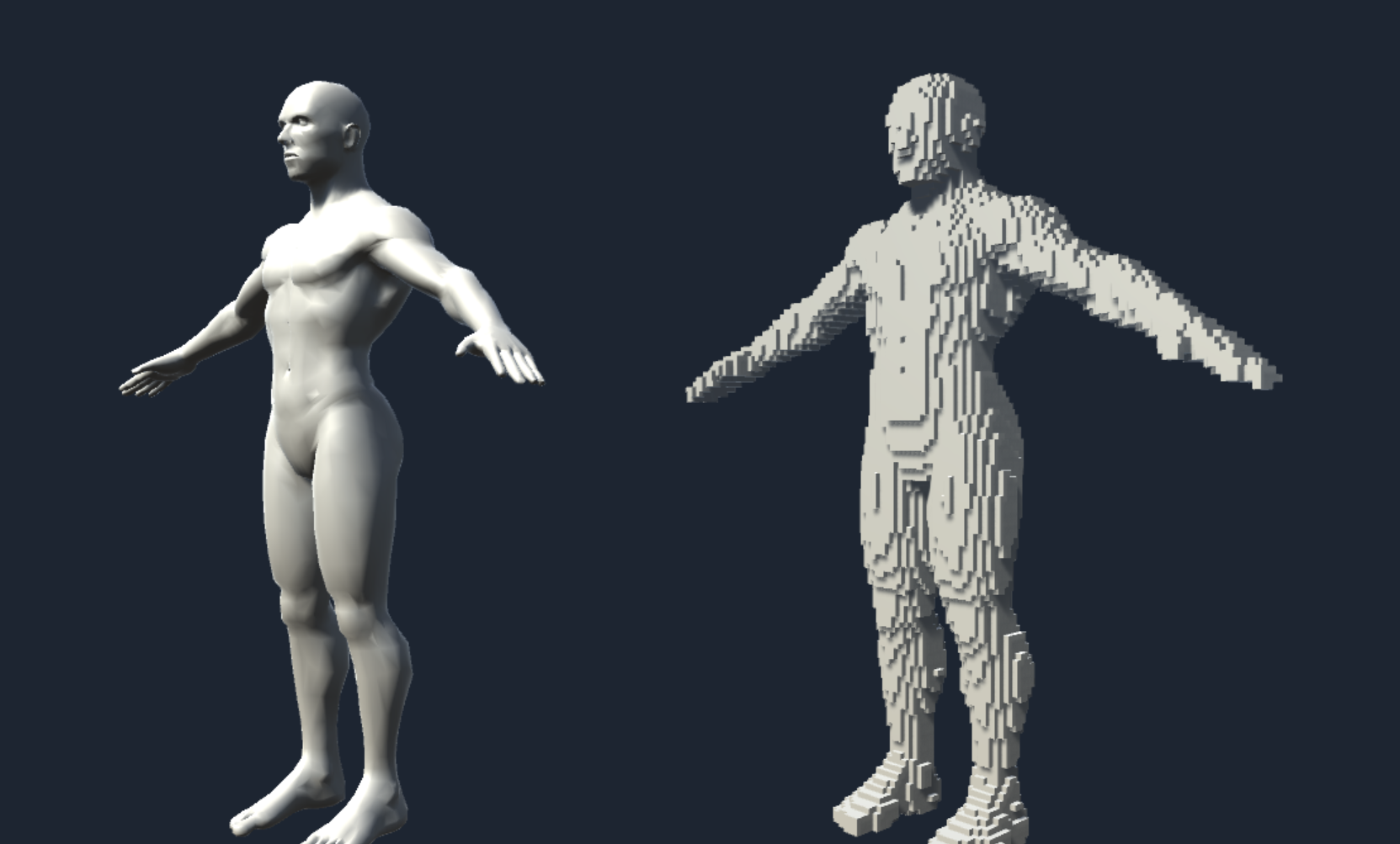
Figure 1.15: Demo of voxel data obtained by CPUVoxelizer.Voxelize visualized as a mesh (CPUVoxelizerTest.scene)
The VoxelMesh class describes the process of constructing a mesh based on the voxel data array Voxel_t [] and the unit length information of one voxel.
CPUVoxelizerTest.cs in the previous section uses this class to generate voxel mesh.
VoxelMesh.cs
public class VoxelMesh {

    public static Mesh Build (Voxel_t[] voxels, float size)
    {
        var hsize = size * 0.5f;
        var forward = Vector3.forward * hsize;
        var back = -forward;
        var up = Vector3.up * hsize;
        var down = -up;
        var right = Vector3.right * hsize;
        var left = -right;

        var vertices = new List<Vector3>();
        var normals = new List<Vector3>();
        var triangles = new List<int>();

        for(int i = 0, n = voxels.Length; i < n; i++)
        {
            if(voxel[i].fill == 0) continue;

            var p = voxels[i].position;

            // The vertices of the eight corners that make up the Cube that represents one voxel
            var corners = new Vector3[8] {
                p + forward + left + up,
                p + back + left + up,
                p + back + right + up,
                p + forward + right + up,

                p + forward + left + down,
                p + back + left + down,
                p + back + right + down,
                p + forward + right + down,
            };

            // Build the 6 faces that make up the Cube

            // up
            AddTriangle(
                corners[0], corners[3], corners[1],
                up, vertices, normals, triangles
            );
            AddTriangle(
                corners[2], corners[1], corners[3],
                up, vertices, normals, triangles
            );

            // down
            AddTriangle(
                corners[4], corners[5], corners[7],
                down, vertices, normals, triangles
            );
            AddTriangle(
                corners[6], corners[7], corners[5],
                down, vertices, normals, triangles
            );

            // right
            AddTriangle(
                corners[7], corners[6], corners[3],
                right, vertices, normals, triangles
            );
            AddTriangle(
                corners[2], corners[3], corners[6],
                right, vertices, normals, triangles
            );

            // left
            AddTriangle(
                corners[5], corners[4], corners[1],
                left, vertices, normals, triangles
            );
            AddTriangle(
                corners[0], corners[1], corners[4],
                left, vertices, normals, triangles
            );

            // forward
            AddTriangle(
                corners[4], corners[7], corners[0],
                forward, vertices, normals, triangles
            );
            AddTriangle(
                corners[3], corners[0], corners[7],
                forward, vertices, normals, triangles
            );

            // back
            AddTriangle(
                corners[6], corners[5], corners[2],
                forward, vertices, normals, triangles
            );
            AddTriangle(
                corners[1], corners[2], corners[5],
                forward, vertices, normals, triangles
            );
        }

        var mesh = new Mesh ();
        mesh.SetVertices (vertices);

        // Apply 32bit index format if the number of vertices exceeds the number that can be supported by 16bit
        mesh.indexFormat =
            (vertices.Count <= 65535)
            ? IndexFormat.UInt16 : IndexFormat.UInt32;
        mesh.SetNormals(normals);
        mesh.SetIndices(triangles.ToArray(), MeshTopology.Triangles, 0);
        mesh.RecalculateBounds();
        return mesh;
    }
}
From here, I will explain how to execute voxelization implemented by CPU Voxelizer faster using GPU.
The voxelization algorithm implemented by CPUVoxelizer can be parallelized for each coordinate in the lattice space separated by the unit length of voxels on the XY plane.
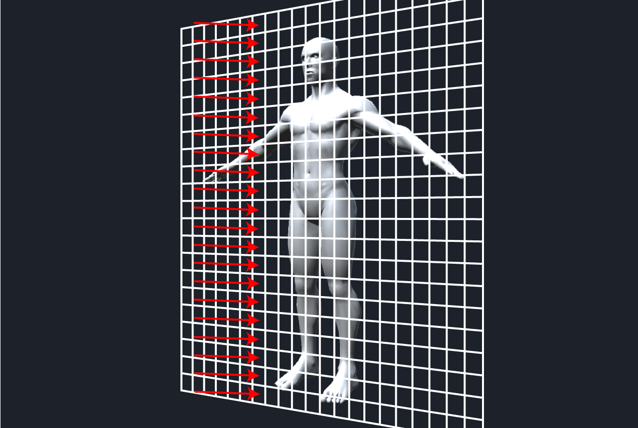
Figure 1.16: Lattice space delimited by unit length of voxels on the XY plane. Voxelization can be parallelized for each lattice, so GPU implementation is possible.
If you allocate each process that can be parallelized to the GPU thread, you can execute the process at high speed thanks to the high-speed parallel computing of the GPU.
The implementation of voxelization on GPU is described in GPU Boxelizer.cs and Voxelizer.compute.
(The basics of Compute Shader, which appears in this section and is indispensable for GPGPU programming in Unity, are explained in Unity Graphics Programming vol.1 "Introduction to Compute Shader")
Voxelization on GPU is a static function of GPUVoxelizer class
GPUVoxelizer.cs
public class GPUVoxelizer
{
    public static GPUVoxelData Voxelize (
        ComputeShader voxelizer,
        Mesh mesh,
        int resolution
    ) {
    ...
    }
}
Execute by calling. When executed with Voxelizer.compute, the mesh to be voxelized, and the resolution specified as arguments, GPUVoxelData indicating voxel data is returned.
Follow the general flow of voxelization (1) to (3) to set up the data required for voxel generation.
GPUVoxelizer.cs
public static GPUVoxelData Voxelize (
    ComputeShader voxelizer,
    Mesh mesh,
    int resolution
) {
    // Same process as CPUVoxelizer.Voxelize -------
    mesh.RecalculateBounds();
    var bounds = mesh.bounds;

    float maxLength = Mathf.Max(
        bounds.size.x,
        Mathf.Max(bounds.size.y, bounds.size.z)
    );
    var unit = maxLength / resolution;

    var hunit = unit * 0.5f;

    var start = bounds.min - new Vector3 (unit, unit, unit);
    var end = bounds.max + new Vector3 (unit, unit, unit);
    var size = end - start;

    int width = Mathf.CeilToInt(size.x / unit);
    int height = Mathf.CeilToInt(size.y / unit);
    int depth = Mathf.CeilToInt(size.z / unit);
    // ------- So far the same as CPUVoxelizer.Voxelize
    ...
}
The array of Voxel_t is defined as ComputeBuffer so that it can be handled on the GPU. The point to note here is that the Voxel_t array generated as a 3D array is defined as a 1D array in the CPU implementation.
This is because it is difficult for GPUs to handle multidimensional arrays, so define it as a one-dimensional array and get the index on the one-dimensional array from the three-dimensional position (x, y, z) in Compute Shader. By doing so, the one-dimensional array is processed like a three-dimensional array.
GPUVoxelizer.cs
// Generate a ComputeBuffer representing a Voxel_t array
var voxelBuffer = new ComputeBuffer(
    width * height * depth,
    Marshal.SizeOf(typeof(Voxel_t))
);
var voxels = new Voxel_t[voxelBuffer.count];
voxelBuffer.SetData (voxels); // Initialize
Transfer these set up data to the GPU side.
GPUVoxelizer.cs
// Transfer voxel data to GPU side
voxelizer.SetVector("_Start", start);
voxelizer.SetVector("_End", end);
voxelizer.SetVector("_Size", size);

voxelizer.SetFloat("_Unit", unit);
voxelizer.SetFloat("_InvUnit", 1f / unit);
voxelizer.SetFloat ("_ HalfUnit", unit);
voxelizer.SetInt("_Width", width);
voxelizer.SetInt("_Height", height);
voxelizer.SetInt("_Depth", depth);
Generate a Compute Buffer that represents the mesh in order to determine the intersection of the triangles and voxels that make up the mesh.
GPUVoxelizer.cs
// Generate a ComputeBuffer that represents the vertex array of the mesh
var vertices = mesh.vertices;
var vertBuffer = new ComputeBuffer(
    vertices.Length,
    Marshal.SizeOf(typeof(Vector3))
);
vertBuffer.SetData(vertices);

// Generate a ComputeBuffer that represents a triangular array of meshes
var triangles = mesh.triangles;
var triBuffer = new ComputeBuffer(
    triangles.Length,
    Marshal.SizeOf(typeof(int))
);
triBuffer.SetData(triangles);
In the process of generating voxels located on the surface of the mesh on the GPU, after generating voxels that intersect the front-facing triangle, the voxels that intersect the back-facing triangle are generated.
This is because the value of the front flag written to the voxel may not be uniquely determined when multiple triangles intersect for the voxel at the same position.
One thing to keep in mind when using GPU parallel computing is the indefiniteness of the results due to multiple threads accessing the same data at the same time.
In the process of generating this surface, priority is given to the value of the front flag being the back (false), and voxel generation is executed in the order of front → back to prevent indeterminacy of the result.
Transfer the mesh data you just generated to the GPU kernel SurfaceFront, which creates voxels that intersect the front-facing triangles.
GPUVoxelizer.cs
// Transfer mesh data to GPU kernel SurfaceFront
var surfaceFrontKer = new Kernel(voxelizer, "SurfaceFront");
voxelizer.SetBuffer(surfaceFrontKer.Index, "_VoxelBuffer", voxelBuffer);
voxelizer.SetBuffer(surfaceFrontKer.Index, "_VertBuffer", vertBuffer);
voxelizer.SetBuffer(surfaceFrontKer.Index, "_TriBuffer", triBuffer);

// Set the number of triangles that make up the mesh
var triangleCount = triBuffer.count / 3; // (the number of vertex indexes that make up the triangle / 3) is the number of triangles
voxelizer.SetInt("_TriangleCount", triangleCount);
This process is performed in parallel for each triangle that makes up the mesh. Set the kernel thread group to (triangleCount / number of kernel threads + 1, 1, 1) so that all triangles are processed and run the kernel.
GPUVoxelizer.cs
// Build a voxel that intersects a front-facing triangle
voxelizer.Dispatch(
    surfaceFrontKer.Index,
    triangleCount / (int)surfaceFrontKer.ThreadX + 1,
    (int)surfaceFrontKer.ThreadY,
    (int)surfaceFrontKer.ThreadZ
);
Since the SurfaceFront kernel only processes triangles that are facing the front, it checks the front and back of the triangle, returns to finish the process if it is the back, and builds the mesh surface if it is the front. Is running.
Voxelizer.compute
[numthreads(8, 1, 1)]
void SurfaceFront (uint3 id : SV_DispatchThreadID)
{
    // return if the number of triangles is exceeded
    int idx = (int)id.x;
    if(idx >= _TriangleCount) return;

    // Get the vertex position of the triangle and the front and back flags
    float3 va, vb, vc;
    bool front;
    get_triangle(idx, va, vb, vc, front);

    // return if it is on the back
    if (!front) return;

    // Build a mesh surface
    surface(va, vb, vc, front);
}
The get_triangle function gets the vertex position and front / back flag of the triangle based on the mesh data (_TriBuffer representing the vertex index that constitutes the triangle and _VertBuffer representing the vertex) passed from the CPU to the GPU side.
Voxelizer.compute
void get_triangle(
    int idx,
    out float3 va, out float3 vb, out float3 vc,
    out bool front
)
{
    int ia = _TriBuffer[idx * 3];
    int ib = _TriBuffer[idx * 3 + 1];
    int ic = _TriBuffer[idx * 3 + 2];

    va = _VertBuffer [ia];
    vb = _VertBuffer[ib];
    vc = _VertBuffer[ic];

    // Determine if the triangle is front or back when viewed from the forward (0, 0, 1) direction
    float3 normal = cross ((vb - va), (vc - vb));
    front = dot(normal, float3(0, 0, 1)) < 0;
}
The surface function that determines the intersection of a voxel and a triangle and writes the result to the voxel data takes time to acquire the index of the voxel data generated as a one-dimensional array, but the content of the process is implemented on the CPU Voxelizer. It will be almost the same as.
Voxelizer.compute
void surface (float3 va, float3 vb, float3 vc, bool front)
{
    // Calculate the triangle AABB
    float3 tbmin = min (min (va, vb), vc);
    float3 tbmax = max(max(va, vb), vc);

    float3 bmin = tbmin - _Start;
    float3 bmax = tbmax - _Start;
    int iminX = round(bmin.x / _Unit);
    int iminY = round(bmin.y / _Unit);
    int iminZ = round(bmin.z / _Unit);
    int imaxX = round(bmax.x / _Unit);
    int imaxY = round(bmax.y / _Unit);
    int imaxZ = round(bmax.z / _Unit);
    iminX = clamp(iminX, 0, _Width - 1);
    iminY = clamp(iminY, 0, _Height - 1);
    iminZ = clamp(iminZ, 0, _Depth - 1);
    imaxX = clamp(imaxX, 0, _Width - 1);
    imaxY = clamp(imaxY, 0, _Height - 1);
    imaxZ = clamp(imaxZ, 0, _Depth - 1);

    // Judge the intersection with voxels in the triangular AABB
    for(int x = iminX; x <= imaxX; x++) {
        for(int y = iminY; y <= imaxY; y++) {
            for(int z = iminZ; z <= imaxZ; z++) {
                // Generate AABB for voxels located at (x, y, z)
                float3 center = float3(x, y, z) * _Unit + _Start;
                AABB aabb;
                aabb.min = center - _HalfUnit;
                aabb.center = center;
                aabb.max = center + _HalfUnit;
                if(intersects_tri_aabb(va, vb, vc, aabb))
                {
                    // Get the index of a one-dimensional voxel array from the position of (x, y, z)
                    uint vid = get_voxel_index(x, y, z);
                    Voxel voxel = _VoxelBuffer[vid];
                    voxel.position = get_voxel_position(x, y, z);
                    voxel.front = front;
                    voxel.fill = true;
                    _VoxelBuffer[vid] = voxel;
                }
            }
        }
    }
}
Now that we have generated voxels for the front-facing triangles, let's move on to the back-facing triangles.
Transfer the mesh data to the GPU kernel SurfaceBack, which generates voxels that intersect the triangle facing the back, and execute it as before.
GPUVoxelizer.cs
var surfaceBackKer = new Kernel(voxelizer, "SurfaceBack");
voxelizer.SetBuffer(surfaceBackKer.Index, "_VoxelBuffer", voxelBuffer);
voxelizer.SetBuffer(surfaceBackKer.Index, "_VertBuffer", vertBuffer);
voxelizer.SetBuffer(surfaceBackKer.Index, "_TriBuffer", triBuffer);
voxelizer.Dispatch(
    surfaceBackKer.Index,
    triangleCount / (int)surfaceBackKer.ThreadX + 1,
    (int)surfaceBackKer.ThreadY,
    (int)surfaceBackKer.ThreadZ
);
The processing of SurfaceBack is the same as SurfaceFront except that it returns a return when the triangle is facing the front. By running SurfaceBack after SurfaceFront, the voxel's front flag will be overridden by SurfaceBack, even if there are voxels that intersect both the front-facing triangle and the back-facing triangle. It will be prioritized to face the back.
Voxelizer.compute
[numthreads(8, 1, 1)]
void SurfaceBack (uint3 id : SV_DispatchThreadID)
{
    int idx = (int)id.x;
    if(idx >= _TriangleCount) return;

    float3 va, vb, vc;
    bool front;
    get_triangle(idx, va, vb, vc, front);

    // return if front
    if (front) return;

    surface(va, vb, vc, front);
}
The volume kernel is used to fill the inside of the mesh.
The Volume kernel prepares and executes a thread for each coordinate in the lattice space separated by the unit length of voxels on the XY plane. In other words, in the case of CPU implementation, the place where the double loop was executed for XY coordinates is parallelized by GPU and speeded up.
GPUVoxelizer.cs
// Transfer voxel data to Volume kernel
var volumeKer = new Kernel(voxelizer, "Volume");
voxelizer.SetBuffer(volumeKer.Index, "_VoxelBuffer", voxelBuffer);

// Fill the inside of the mesh
voxelizer.Dispatch(
    volumeKer.Index,
    width / (int)volumeKer.ThreadX + 1,
    height / (int)volumeKer.ThreadY + 1,
    (int)volumeKer.ThreadZ
);
The Volume kernel implementation is similar to the one implemented in GPU Foxelizer.
Voxelizer.compute
[numthreads(8, 8, 1)]
void Volume (uint3 id : SV_DispatchThreadID)
{
    int x = (int)id.x;
    int y = (int)id.y;
    if(x >= _Width) return;
    if(y >= _Height) return;

    for (int z = 0; z < _Depth; z++)
    {
        Voxel voxel = _VoxelBuffer[get_voxel_index(x, y, z)];
        // Almost the same processing as in CPUVoxelizer.Voxelize continues
        ...
    }
}
Once the voxel data is obtained in this way, it discards the mesh data that is no longer needed and generates GPUVoxel Data with the data needed to create the voxel visual representation.
GPUVoxelizer.cs
// Discard mesh data that is no longer needed
vertBuffer.Release();
triBuffer.Release();

return new GPUVoxelData(voxelBuffer, width, height, depth, unit);
This completes voxelization by GPU implementation. Voxel data is actually visualized using GPU VoxelData in GPUVoxelizerTest.cs.
In the test scene, Voxelizer is executed at the time of Play, so it is difficult to understand the speed difference between CPU implementation and GPU implementation, but GPU implementation has achieved considerable speedup.
Performance depends greatly on the execution environment, the number of polygons in the mesh to be voxelized, and the resolution of voxelization.
Under these conditions, the GPU implementation is running 50 times faster than the CPU implementation.
Introducing an application example (GPUVoxelParticleSystem) using the GPU-implemented ParticleSystem.
The GPU Voxel Particle System uses the Compute Buffer, which represents the voxel data obtained from the GPU Voxelizer, to calculate the position of particles in the Compute Shader.
I am creating an effect in the flow.
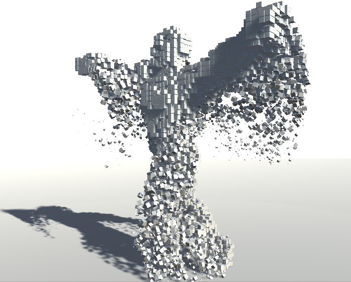
Figure 1.17: Application example using ParticleSystem of GPU implementation (GPUVoxelParticleSystem)
By making a large number of particles appear from the voxel position, a visual like an animation model composed of particles is realized.
Voxels can be applied to the animation model frame by frame only because of the speedup by implementing the GPU, and in order to expand the range of visual expressions that can be used in real time, such speedup on the GPU is indispensable. It has become a thing.
In this chapter, we introduced the algorithm for voxelizing the mesh model using CPU implementation as an example, and even speeded up voxelization by GPU implementation.
We took the approach of generating voxels using the intersection judgment of triangles and voxels, but there is also a method of constructing voxel data by rendering the model from the XYZ directions into a 3D texture by parallel projection.
The method introduced in this chapter has a problem in how to apply a texture to the voxelized model, but if the method renders the model to a 3D texture, coloring the voxels is easier and more accurate. You may be able to do it.